PAVING THE WAY

Since 1979, Almond Engineering Ltd have become industry leaders in precision engineering across a multitude of sectors from Aerospace & Defence to Oil & Gas.  They are renowned for their meticulous attention to detail with their innovative and bespoke solutions in automation, design, fabrication, site installation and vacuum forming.  When they engaged us to install additional car parking at their facility in Livingston it was evident it would need to be load bearing to commercial specifications.  Below are pictures of the process from start to finish with brief explanation.
This is the area where the car park was to be installed.  Multiplying the length (5m) by the width (15m) gave us a surface area of 75m². That enabled us to also calculate the volume (length x width x depth) of materials required. We used fencing pins to mark off the area. Pythagorean theorem verified our corners were at 90° which meant the pins and string Iines were where they needed to be and we could begin work.  
We had to prepare the site for construction. To achieve this, we excavated approx. 60 tonnes of material (tonne being metric 1000kg and not the imperial ton). An excavator and a Hi-Lift dumper made light work of the heavy load. Ground protection mats were used at the base of the waste and this was then fenced off until the grab lorry came to dispose of the waste.
The black fabric is a non-woven geotextile membrane made from polypropylene.  This is essential for the best performance in ground stabilisation and works by preventing sinking and rutting caused by the settlement of aggregates. It also provides good performance in weed suppression, filtration and drainage.  
The layer of stones you can see being loaded onto the surface of the membrane is known as the sub-base and it’s made from Ministry of Transport (MOT) Type 1.  It’s a crushed material that is 0-40mm in size and usually made from granite or limestone.  This makes it an extremely strong and hardwearing surface when compacted.  
The next step is to install the kerb edgers.  The process for this starts with laying a bed of concrete on top of the initial layer of compacted sub-base of MOT Type 1 so the kerb edgers have something with adhesive properties to stick to.  A spirit level was used on the surface to ensure the 15m rear side was level (the two other 5m sides slope down towards the drainage channel).  Using two string lines we were able to mark the height that the sub-base had to be build up to and also mark the finished height of the surface of the monoblocks.  We have also put concrete on either side of the edgers for support then back filled the rear with soil for grass to grow on. 

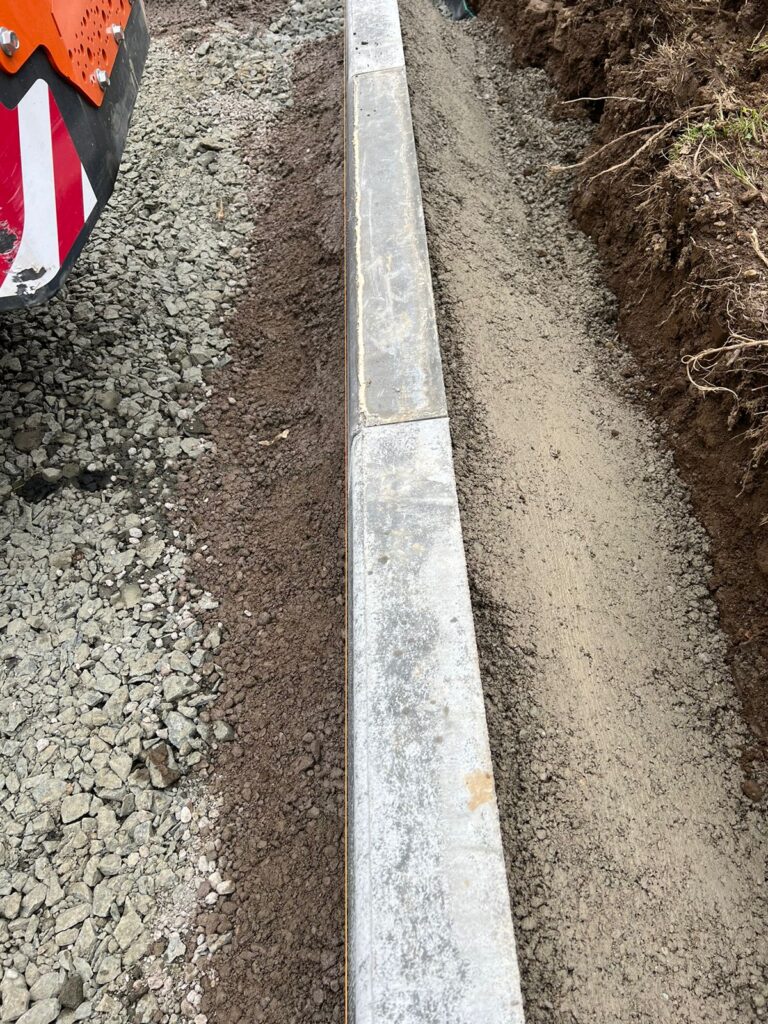
The kerb edgers are made of concrete that offers high compressive strength, conforming to BS EN 1340-2003 thanks to a hydraulic press which ensures long-term performance.  We also added a quadrant kerb for the corner because its rounded surface will be kinder to car tyres than the right-angled alternative.

To make the concrete we used cement and ballast at a ratio of 1:4. The cement used conforms to BS EN 9001 and is recommended for use in concrete.  The ballast is a mixture of concrete sand (also known as sharp sand) and gravel (10-20mm shingle).  The 1:4 mix is the industry standard but we like to go the extra mile so we add two special ingredients:

Plasticiser is added because it offers a greater consistency to the mix, increases workability and reduces cracking.

We added SBR (systreme-butadiene rubber) to significantly enhance the adhesive strength of the concrete to the kerb edgers.  It also improves frost resistance because its latex based and therefore water resistant in areas subject to humidity, dampness and continuous water contact.  
The next step was to add the base layer.  This was a mixture of concrete sand and granite dust.  The metal poles are our screed bars and represent the finished height the base layer was to meet.  We put the concrete sand/granite dust mix where needed then spread it around and compacted it with the vibration plate.  Thereafter, it was screeded to ensure it was of consistent height.  Any deviations were topped up and compacted again before being screeded again.  Once this was perfect it was time to lay the block paving.
Now that the edgers were in place on all three sides we had to build up the sub-base by adding and compacting layers of MOT Type 1 in compacted layers until we had a total of 150mm (6”) of sub-base.  In the absence of a Hiab (w power loader-crane that uses hydraulics to move materials from A to B), a forklift was used to move the bulk bags to where they were required. If anyone asks the forklift definitely did not get stick and need pulled out with the digger and a tow strap.  
Everything up to this point has been preparation.  Now we can lay the block paving. This is incredibly satisfying and created a massive visual impact.  The methodical process begins with the outside edge which in this design is referred to as a soldier course.  The blocks must be capable of withstanding lateral pressures exerted by vehicles moving on them.  This is achieved with the retaining edge.  The outer defence is the commercial kerb edging which also has concrete haunching for retention, mixed to our specifications.  The inner defence is the soldier course of monoblocks that make up the four sides.  The paving itself is then laid at 90° to the soldier course.  The pattern used is called “Herringbone”, which is a fully interlocking pattern. We made a conscious decision to use this pattern when laying because it doesn’t shift out of alignment even when under heavy loads due to its interlocking nature.  Coincidentally it’s also a rather eye-catching design.  We have used a contrasting colour of blocks to separate the parking spaces.  In this case we used “brindle” for the car park and “buff” for the lines.  To finish off we brushed kiln dried sand into all of the gaps, went over the entire surface with the vibrating compactor again followed by another round of kiln dried sand to ensure stability.